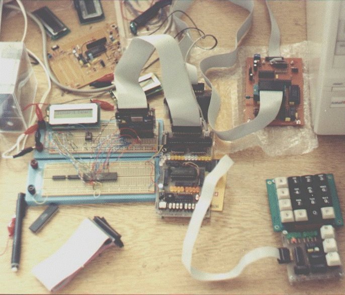
Here is the first Z80 circuit I have ever built. Plugged to the breadboard is the Z80 module with oscillator and reset button. This module has all the pins of the Z80. I arranged all the pins in a way that it will ease breadboarding. For example all the data and address pins are side by side and in order. The big board in the middle of the photo is the memory board. The 8 switches at the bottom of the board are used to program the RAM in binary, but are not used since I added the keyboard. The keyboard is also obsolete now because I am using the EPROM programmer (the board beside the computer case) to program the RAM.
When I built this circuit I did not have a computer and did not have access to an assembler. When I wrote I program, I would first look up the hex equivalent of the Z80 opcodes to generate the binary listing of the program. Then I would program the RAM byte by byte in binary using 8 data switches. Debugging and changing the code was difficult because it usually required that I rewrite the hex listing from scratch.
Today I own a PC, and still use this circuit. Loading my code to the RAM of the Z80 is a matter of seconds...
Actually, my school project was the same circuit. The main difference is that it is built on a PCB and the obsolete parts (12 bit programmable counter, keyboard and a bunch of switches) of this circuit are omitted.