Here are the properties of my Z80 project:
- Uses windows based software and EPP mode
printer port to load /retrieve the code
- A total of 16kb memory is available. It
can be all RAM or 8Kb RAM/8Kb ROM. RAM and ROM are interchangeable
without any modifications to the hardware.
- It is possible to alter the memory map of
the system ie. Z80 can start execution either from the RAM or ROM.
- 2 8255 chips provide 48 I/O pins
- A 2*16 dot matrix LCD,8 buttons and 8 LEDs
occupy 27 I/O pins and 21 I/O pins are available to connect other
I/O devices.
- May double as a an EPROM programmer, because
it actually has a built in EPROM programmer (the one published in
Elektor, March 1997). 12,5 V EPROMs can be programmed easily. It is
also possible to program EPROMs up to 64Kb, but this feature was not
implemented since It will require dip switches and probably some glue
logic.
My project has a very simple operating
principle. Both the Z80 and the programmer are connected to the memory
the usual way, but there is a simple logic circuit that controls their
access to the memory. While the programmer has access to the memory,
Z80 is hold in reset state. In this state, it is possible to program/read
any memory cell to place the code and data for Z80 to process. When
the programmer releases the memory, Z80 recovers from the reset state
and starts executing the code in the memory. Switching between the programmer
and the Z80 run modes is done by toggling a switch. When one part is
active, the other part goes tri-state.
The first Z80 board I built did not
have an EPROM programmer to load the code. I used 8 switches to write
the code in binary and used a programmable counter to access the whole
8 Kb of memory. Then I built a keyboard using a 74C922 chip and a simple
circuit to convert the 4-bit output of the 74C922 to 8-bit data. This
dramatically increased the time it took to load the code into the memory.
But I still had to use the programmable counter to set the adress. Later
I discovered that the EPROM programmer designed by A.Rijfkogel (published
in Elektor, March 1997) employed a programming algorithm perfectly suitable
to program RAM chips. So I added a small buffer circuit to my first
circuit to use it with the EPROM programmer. I managed to get them to
work together without any modifications to the EPROM programmer. Is
this what they call "applied reverse engineering" ?
By now, I referred to this project
as mine but this year I did not work on the school project alone. I
had a partner, Caner Buyuktuna. His major input was in PCB design and
some coding.
After designing and building our circuit,
we could not get it to work. We had made a mistake and we had to cut
some tracks and add in two 74245 buffer chips to make the circuit work.
The time we had to finish our project was limited and we did not have
time to correct our PCB/Schematic and build a new circuit. This is why
schematics and complete PCBs are not available here. All we can supply
are the subcircuits we used with a few modifications to create our project
.
When we got the circuit to work we
started to code small programs to show our teachers/friends what can
be done with our project. Here is what we did:
- Interfaced a Hitachi HD44780 based
2*16 dot matrix LCD module
- Made simple animations on that
display
- We converted the analog position
of a potentiometer in to a number relative to its position(i.e. we
digitized it) without using an ADC chip(Very useful for a lot of applications)
- Played WAVE files with a R-2R DAC
connected to one of the 8255 ports
- Made a simple keyboard to play
simple music notes. I can not say it is calibrated. My ear is not
good at such stuff. We only wrote code that produces a different frequency
on every key pressed
- Turned a step motor, and made its
speed adjustable with that pot we digitized
- Made some LEDs blink /scroll and
some other simple stuff
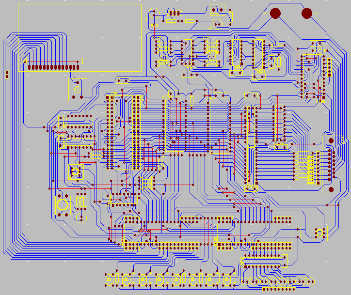
Click HERE to
see a the pcb from a Traxmaker screenshot .
Click HERE to see a photo of the first Z80 board
I built.
Click HERE to see/get the available project
files