INTRODUCTION
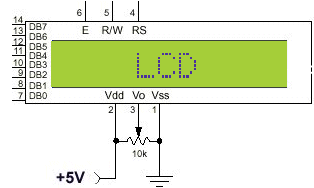
Any parallelly interfaced character LCD you get these days will have a Hitachi HD44780 chip or a different one compatible with the HD44780. These usually have 14 pins as shown below.
Essentials:
Display Data RAM (DDRAM)
Display data RAM (DDRAM) is where you send the characters (ASCII code) you want to see on the LCD screen. It stores display data represented in 8-bit character codes. Its capacity is 80 characters (bytes). Bonus: The area in display data RAM (DDRAM) that is not used for display can be used as general data RAM. DD RAM address is the position of the cursor (i.e. where the data you sent will be displayed). Below you see DD RAM address layout of a 2*16 LCD.
Character Generator RAM (CGRAM)
In the character generator RAM, the user can define his/her own character patterns by program. CG RAM is 64 bytes ,allowing for eight 5*8 pixel,character patterns to be defined. See my "Defining custom characters" and "Creating Animations" pages for more info on CG RAM.
Registers
The HD44780 has two 8-bit registers, an instruction register (IR) and a data register (DR). The IR stores instruction codes, such as display clear and cursor shift, and address information for display data RAM (DDRAM) and character generator RAM (CGRAM). The DR temporarily stores data to be written into DDRAM or CGRAM and temporarily stores data to be read from DDRAM or CGRAM. Data written into the DR is automatically written into DDRAM or CGRAM by an internal operation. The DR is also used for data storage when reading data from DDRAM or CGRAM. These two registers can be selected by the register selector (RS) signal. See the table below:
Operation IR write as an internal operation (display clear, etc.) Read busy flag (DB7) and address counter (DB0 to DB6) DR write as an internal operation (DR to DDRAM or CGRAM) DR read as an internal operation (DDRAM or CGRAM to DR)
Busy Flag (BF)
When the busy flag is 1, the HD44780U is in the internal operation mode, and the next instruction will not be accepted. When RS = 0 and R/W = 1 (see the table above), the busy flag is output to DB7 (MSB of LCD data bus). The next instruction must be written after ensuring that the busy flag is 0.
Address Counter (AC)
The address counter (AC) assigns addresses to both DDRAM and CGRAM. When a "set DD RAM/CG RAM address" instruction is written into the IR, the address information is sent from the IR to the AC. Selection of either DDRAM or CGRAM is also determined concurrently by the instruction. After writing into (or reading from) DDRAM or CGRAM, the AC is automatically incremented (or decremented) by 1 . The AC contents are output to DB0 to DB6 when RS = 0 and R/W = 1 (see the table above). To see the effects of setting the address counter to increment or decrement , see the HD44780 commands page.
To display a character,
positional data is written into IR (DDRAM address). A character code is then written into DR and the LCD unit displays the corresponding pattern at the specified location. The LCD unit can either increment or decrement the display position after each character entry (see the entry mode set command), so that only successive character codes need to be entered to display a continuos character string. See the Z80 Examples page for examples in Z80 assembly.
Prior to writing characters to the display, it must be initialized. To initialize the display you must learn about the commands first.
Character Type LCD:
Graphics LCD: (Based on: KS0108, HD61202 and similars...)

